Turbine Flow Meter
2024年9月25日
Super-Thin Safety Light Curtain
2024年10月14日Electronic Flow Meter
Pneumatic-hydraulic dual-purpose type, can be used in pneumatic and hydraulic systems, can be used for circulating water, cutting fluid and lubricating oil flow monitoring, as well as pump idling protection.
$45.00
Theory
Based on the thermal principle, the closed probe contains two resistors, one of which is heated as a detection resistor and the other unheated as a reference resistor, and when the medium flows, the heat is carried away from the heated resistor. The resistance value is changed and the difference between the two resistors is used as a basis for determining the flow rate.
Product feature
No moving parts, maintenance-free, easy to install, a model for a variety of pipe diameter requirements, switching volume continuously adjustable, very low pressure loss, compact structure LED display flow trend and switching status.
Application
Pneumatic-hydraulic dual-purpose type, can be used in pneumatic and hydraulic systems, can be used for circulating water, cutting fluid and lubricating oil flow monitoring, as well as pump idling protection.
Specifications
| Setting range | 1-150cm/s(water),3-300cm/s(oil),20-2000cm/s(air) |
| Signal Output | PNP,NPN,Relay,Normally open + Normally closed(SPDT),4-20mA |
| Power supply | 24V x 20%DC or 230V x 15%AC |
| Turn-on current | 400mA(PNP/NPN type) 4A(Relay) |
| No-load current | Maximum 80mA |
| Flow rate indication | LEDs (6) |
| Setting method | Adjustment potentiometer setting |
| Pressure range | 100bar |
| Temperature gradient | 4°C/S |
| Response time | 1-13S, typical 2S |
| Initialization time | 8S |
| Electrical protection | Inverted phase protection, short circuit protection, overload protection |
| Protection class | IP67 |
| Medium temperature | -20℃–80℃ |
| Ambient temperature | -20℃–80℃ |
| Storage temperature | -20℃–100℃ |
| Wiring method | M12 connector / directly attached to the line 2M optional |
| Material | Sensor: stainless steel Shell body: PBT |
| Weight | 278g |
Model Selection
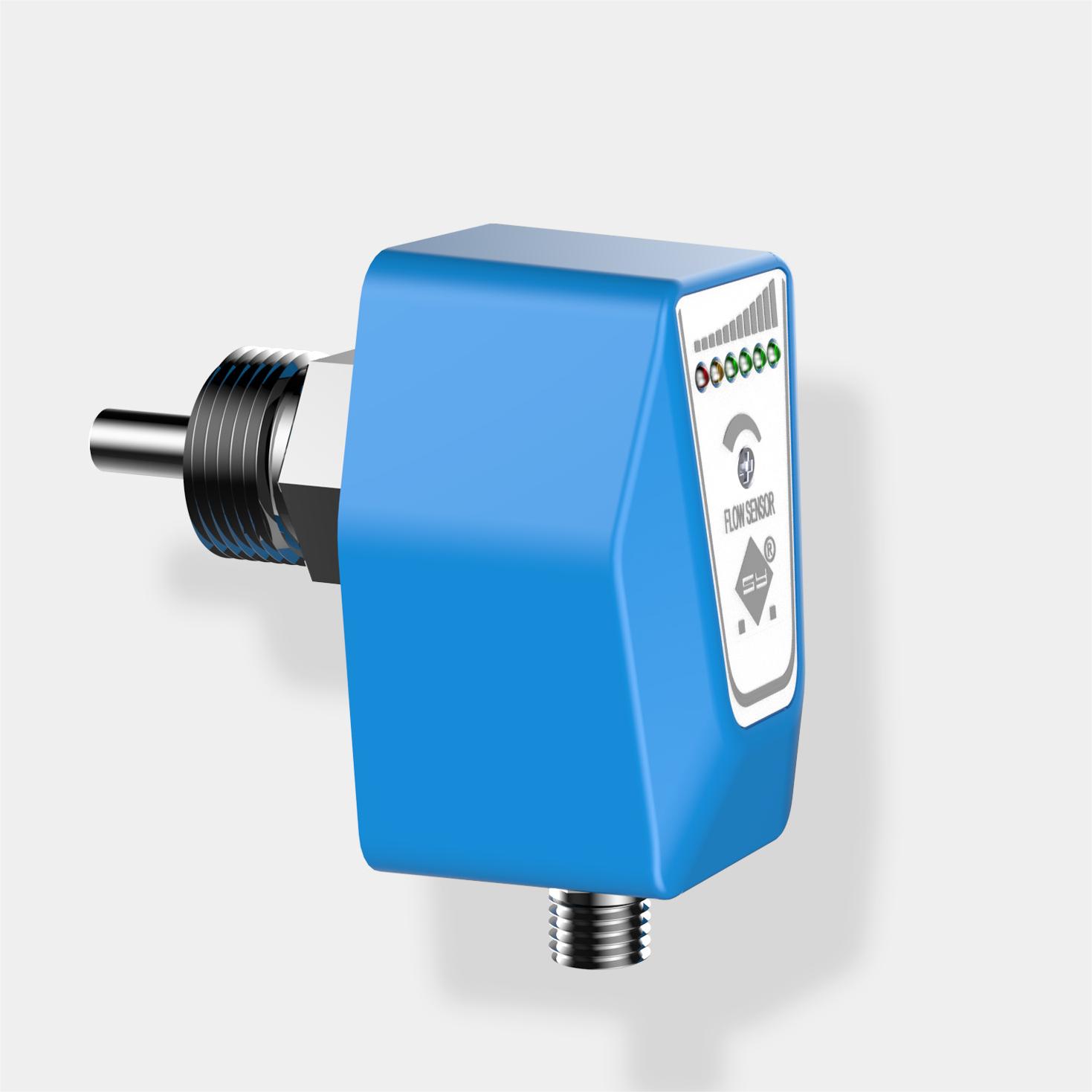
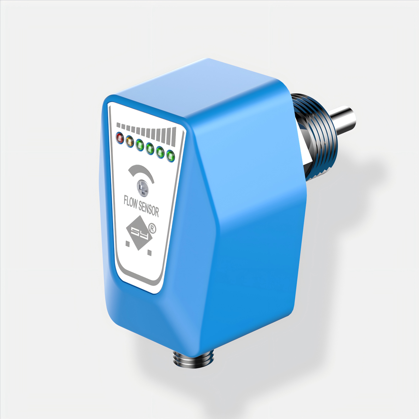
For flow switches with outputs in the form of PNP, NPN and relays, the meaning of the LED indication is as follows: Red on Flow rate below set point (transistor does not conduct/relay does not operate) Flow rate is equal to or higher than set point (transistor energized/relay operates) Yellow and green lamps are on The extent to which the flow rate exceeds the set point (green lamps 1, 2, 3 or 4 are on together with the yellow lamp) 1. Install the flow switch so that the medium flows at the flow rate that needs to be detected, adjust the potentiometer so that the first green LED lights up just right and the switch is released when the flow rate falls below the current value. If you want to make the switch point is smaller than the current flow rate, you can adjust the potentiometer so that the green LED more bright. 2. If you need to adjust the size of the flow rate, the specific adjustment steps are: unscrew the plastic screws, will be a screwdriver, inserted into the bottom of the product, clockwise adjustment knob, the more the green LED lights the flow rate of the larger, counterclockwise adjustment knob, the less the green LED lights the flow rate of the smaller!


Reviews
There are no reviews yet.